Ultrasonic Wall Thickness Gauges - Knowledge Base
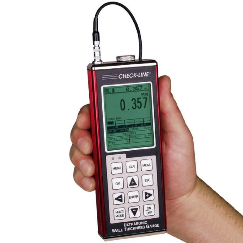
Ultrasonic thickness gauges are the most widely used instruments for non-destructive wall thickness measurement of metals, plastics, composites and other solid materials. They work by sending a high-frequency sound pulse through the material and measuring the time it takes for the echo to return from the opposite surface. This allows precise evaluation of material thickness from one side only, without cutting, drilling or damaging the part.
These instruments are essential for corrosion monitoring, quality control and structural inspection in almost every industrial sector—from shipbuilding and manufacturing to research and development.
Each model differs in measurement range, data features and probe configuration, so understanding how the technology works helps identify the best option for your material and application.
Looking for magnetic wall thickness measurement for non-metallic or transparent materials? See our Magnetic Thickness Gauges Knowledge Base for comparison.
Ultrasonic thickness measurement is a non-destructive testing technique that uses high-frequency sound waves to determine the thickness of solid materials. The gauge sends an ultrasonic pulse through the material and measures the time it takes for the echo to return from the back wall. Since the travel time of the sound is directly proportional to the material’s thickness, the instrument can calculate the wall thickness accurately using the known speed of sound in that material.
1.1 Measurement Principle and Sound Velocity:
Accurate results depend on correctly setting the sound velocity for the test material. Each material has a characteristic speed of sound (for example, about 5,900 m/s for steel and 2,700 m/s for aluminium). Most Checkline gauges include automatic or manual calibration functions that allow you to set this velocity precisely, either by measuring a sample of known thickness or using a certified reference block.
If the velocity is not correctly adjusted, readings may be offset, especially when switching between different materials. For example, a gauge calibrated for steel will show an incorrect thickness if used on plastic or glass without recalibration.
1.2 Suitability of Materials:
Ultrasonic thickness gauges perform best on homogeneous materials such as metals, plastics, glass and ceramics, where sound waves travel uniformly. These materials provide consistent and repeatable readings.
Materials that are porous, fibrous or composite—such as wood, concrete or layered plastics—can scatter or absorb ultrasonic energy, leading to unstable results. In such cases, specialised transducers or alternative methods (like magnetic thickness measurement) may be more appropriate.
1.3 Measurement Range and Accuracy:
The measurable range depends on the transducer frequency, the material’s acoustic properties, and the gauge model.
- Higher frequencies (7–10 MHz) offer excellent resolution for thin walls.
- Lower frequencies (1–5 MHz) provide greater penetration for thick or attenuating materials.
For example, steel can typically be measured from 0.5 mm to over 500 mm with a precision of ±0.01 mm, while cast iron may show larger variations due to its granular structure.
1.4 Coupling Agent:
A coupling agent (couplant) is required to transmit sound efficiently between the probe and the material surface. This thin layer eliminates any air gap that would otherwise reflect the ultrasound. Checkline offers standard gels, high-temperature couplants, and special fluids for rough or curved surfaces. Proper coupling is essential for stable and repeatable results.
1.5 Influence of Temperature:
Temperature affects both the sound velocity and the transducer’s performance. As temperature increases, the speed of sound typically decreases, which can influence measurement accuracy.
For high-temperature applications, it’s important to:
- Use delay-line or high-temperature transducers.
- Apply temperature-resistant couplants.
- Calibrate the gauge at the same temperature as the material.
Maintaining a consistent temperature during measurement ensures reliable results and prolongs probe life.
Advantages:
- Measurement possible from one side only
- High accuracy and repeatability
- Suitable for metallic and non-metallic materials
- Portable and simple to operate
- Fast scanning and data logging options
| Measurement Modes Explained: | |
|---|---|
Pulse-Echo (P-E) Mode This is the most common and basic measurement mode. The transducer sends an ultrasonic pulse through the coating and base material until it reflects from the back wall. The time between the transmitted pulse and the first returning echo determines the total wall thickness — including any coating or paint layer. It is ideal for uncoated materials or where the coating thickness is negligible. Because coatings have slower sound velocity than metals, this mode can overestimate the thickness if used on coated surfaces. | 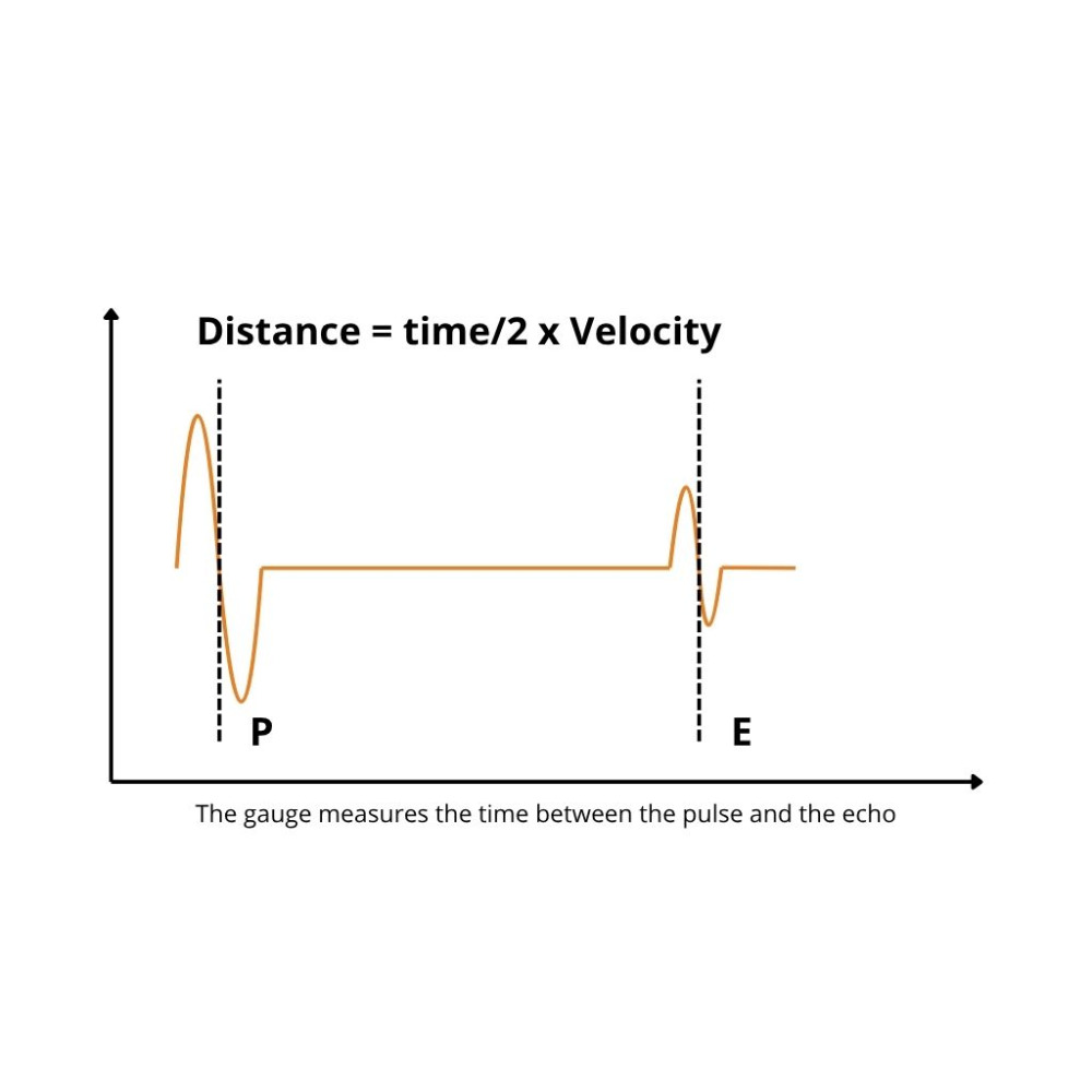 |
Echo-Echo (E-E) Mode Echo-Echo mode measures the time between two successive back-wall echoes, effectively cancelling out the coating layer. Only the thickness of the base material is calculated. This method is particularly useful when testing painted or coated parts, as it eliminates the need to remove the coating before measurement. It requires a clean, well-coupled surface and strong signal reflection to ensure accuracy. |  |
Echo-Echo-Verify (E-E-V or Triple-Echo) Mode An advanced form of Echo-Echo mode that uses a third verification echo to confirm reading stability and eliminate potential false echoes. This mode ensures the most reliable and repeatable results, even under less-than-ideal surface conditions. It is often used in critical safety inspections, such as ship hulls, pipelines, and pressure vessels, where a single incorrect reading could affect compliance or maintenance decisions. | 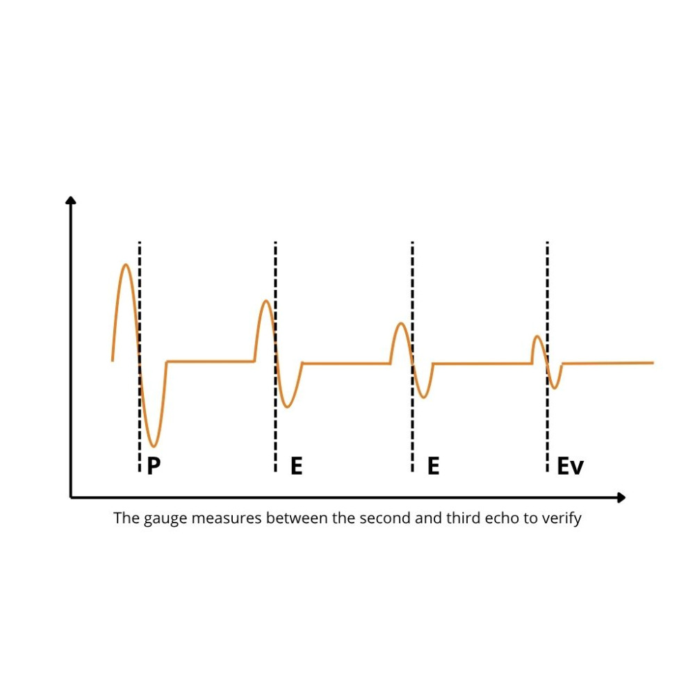 |
Interface-Echo (I-E) Mode This mode measures from the probe’s internal delay line interface to the first back-wall echo of the test material. It is primarily used with delay-line probes for thin materials (down to 0.15 mm) and offers very high resolution. Because the signal path includes the probe’s internal delay, the measurement does not account for any coating or external layer—making it suitable only for uncoated materials and precision laboratory applications. | 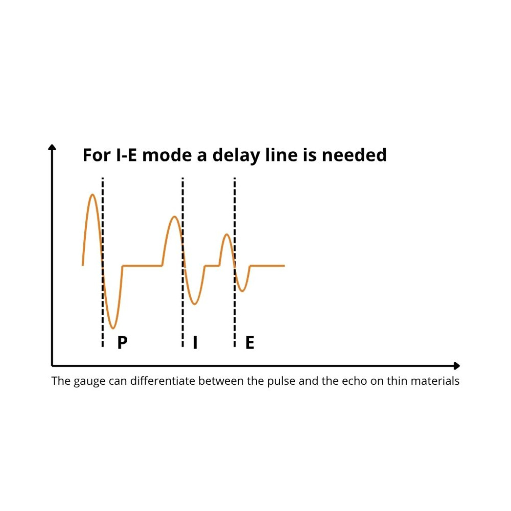 |
Velocity (VX) Mode Instead of measuring thickness, this mode determines the sound velocity of the material. It is used for material characterization, density testing, or temperature correlation studies. Once the correct sound velocity is established, it can be stored in the gauge for precise thickness measurement on that specific material. |
Selecting the right ultrasonic thickness gauge depends on several key factors that influence both accuracy and usability. Choosing a model aligned with your material, environment and reporting requirements ensures precise, repeatable results in any industrial or laboratory setting.
3.1 Key Selection Criteria:
Before choosing a model, consider:
- Material type and expected thickness range – thicker or more attenuating materials (e.g. cast iron) require lower-frequency probes, while thin metals need higher-frequency, delay-line transducers.
- Surface condition – rough, corroded or curved surfaces are best handled by dual-element probes; polished or smooth materials can use single-element probes.
- Presence of coatings – to measure only the base material through paint or protective layers, select a gauge with Echo-Echo or Triple-Echo (E-E-V) capability.
- Data recording and traceability – if measurement logging, statistics or reporting are needed, opt for models with internal memory or USB output.
- Display and analysis features – advanced models offer waveform displays (A-Scan, B-Scan) for visual verification and corrosion profiling.
3.2 Calibration and Accuracy:
Proper calibration is essential for obtaining reliable readings.
Calibration Methods:
- Direct Input: if you already know the exact sound velocity of the material, it can be entered directly on the instrument.
- Sample-Based Calibration: if the sound velocity is unknown, perform a one- or two-point calibration using a reference sample of known thickness. The gauge measures it, compares the result with the known value, and automatically calculates the correct velocity.
- Integrated Zero Plate: most Checkline gauges include a built-in zero reference plate for fast daily calibration and temperature compensation.
Tip: All models from TI-25MX upwards include automatic calibration functions, ensuring precise results across different materials and operating conditions.
3.3 Recommended Model Overview:
The table below provides a simplified guide to help you select the most suitable gauge according to your requirements.
| Model | Measurement Modes | Typical Use Case | Key Advantage | Data Logging |
|---|---|---|---|---|
| TI-25M | Pulse-Echo | Basic, uncoated materials | Simple, cost-effective entry-level model | |
| TI-25MX / MXT | Pulse-Echo / Echo-Echo | Coated materials, general industry | Adds coating compensation | |
| TI-25DLX / DLXT | Pulse-Echo / Echo-Echo | Routine inspection and maintenance | Internal memory, adjustable gain | |
| TI-007X / 007DLX | Pulse-Echo / Interface-Echo | Thin walls, precision testing | Delay-line probe, high-resolution display | |
| TI-PVX / HPX-DLP | Pulse-Echo / Echo-Echo / Echo-Echo-Verify | R&D, quality control labs | A/B-Scan, advanced analysis tools | |
| TI-UMX2 | Pulse-Echo / Echo-Echo / Echo-Echo-Verify | Underwater inspections | Waterproof up to 100 m, integrated logging |
3.4 Choosing by Application:
- General industrial use: TI-25M, TI-25MX
- Coated or corroded surfaces: TI-25DLX, TI-25MXT
- Thin materials or plastics: TI-007X, TI-PVX
- Through-paint and advanced inspections: TI-PVX, HPX-DLP
- Subsea or offshore environments: TI-UMX2
3.5 Final Recommendation:
For routine tasks, the TI-25 Series provides accurate, reliable results at an excellent value.
For more demanding inspection environments—requiring data logging, coating measurement, or waveform visualisation—consider the TI-007X, TI-PVX, or HPX-DLP models.
For underwater or subsea applications, the TI-UMX2 remains the dedicated choice.
Ultrasonic transducers are the key components that transform electrical pulses into ultrasonic waves, and then back into electrical signals after reflection from the material being tested. The correct choice of transducer is essential for obtaining reliable and precise thickness measurements.
4.1 Main Types of Transducers
- Dual-Element Probes
These transducers include two separate crystals—one for transmitting and one for receiving—mounted at a slight angle.
They are ideal for:
• Corroded, rough or curved surfaces, such as pipes, tanks, or structural steel.
• Medium and thick materials, where strong signal penetration is required.
• General-purpose industrial use, as they balance depth capability and accuracy.
| Frequency | Steel | Aluminium | Cast iron | Titan | Plastic | Thin plastic | Glass | Ti-25X series | TI-CMX series | TI-MVX / MMX series |
|---|---|---|---|---|---|---|---|---|---|---|
| 10,0 MHz | ◼ | ◼ | ◼ | |||||||
| 1,00 MHz | ◼ | ◼ | ||||||||
| 2,25 MHz | ◼ | ◼ | ||||||||
| 3,50 MHz | ◼ | ◼ | ||||||||
| 5,00 MHz | ◼ | ◼ | ◼ | |||||||
| 7,50 MHz | ◼ | ◼ | ◼ | ◼ | ||||||
Available Codings (Probe Variants):
|
||||||||||
- Single-Element Probes
A single crystal alternates between transmitting and receiving, offering high precision for homogeneous and smooth materials.
They are used primarily for:
• Thin metals, plastics, and non-ferrous materials like aluminium or titanium.
• High-frequency applications (10–20 MHz) where fine resolution is critical.
| Frequency | Steel | Aluminium | Titan | Thin plastic | TI-007X Series | TI-PVX |
|---|---|---|---|---|---|---|
| 10 MHz | ◼ | ◼ | ◼ | ◼ | ||
| 15 MHz | ◼ | ◼ | ◼ | ◼ | ||
| 20 MHz | ◼ | ◼ | ◼ | ◼ | ||
Available in standard ¼” diameter or pin-type versions (TI-PVX series). |
||||||
- Delay-Line Probes
Used for ultra-thin materials and high-temperature surfaces, these probes include a solid delay block that separates the transducer from the test surface.
This design:
- Enables accurate measurement down to 0.15 mm wall thickness.
- Reduces surface noise and near-surface dead zones.
- Improves performance on small or curved components and hot materials.
4.2 Choosing the Right Transducer
- For corroded or coated metals, select a dual-element probe with 2–5 MHz frequency.
- For thin materials (below 1 mm), use delay-line or high-frequency single-element probes.
- For plastics or composites, opt for lower frequencies (1–2.25 MHz) to enhance penetration.
- For high-temperature or curved applications, specialised delay-line or CPZT probes are recommended.
Advanced ultrasonic thickness gauges not only show numerical readings but also visualise the ultrasonic signal, allowing operators to interpret the material condition in real time.
A-Scan Display
The A-Scan (Amplitude-Time display) shows the returning ultrasonic echoes as a waveform on screen.
Each vertical peak represents a reflection from a material boundary — the first echo usually indicates the surface, while the second marks the back wall or internal layers.
This view allows the operator to:
- Verify signal quality and stability.
- Identify false echoes, noise or structural defects.
- Adjust gain and filtering for challenging materials such as rubber, cast iron, composites or coarse-grain metals.
The A-Scan is a point inspection tool: the transducer must remain stationary on the surface to capture an accurate waveform. It is ideal for complex or attenuative materials where automated readings may be unstable.
A-Scan capability is available on advanced models such as TI-PVX, TI-MVX and the TI-CMX-DLP / CMX-DLP-C, providing professional-grade control over signal interpretation and calibration.
B-Scan Display
The B-Scan creates a two-dimensional cross-section of wall thickness along a scanned path.
As the probe moves across the surface, the instrument continuously records thickness readings and converts them into a greyscale or colour image.
This mode is especially useful for:
- Mapping corrosion profiles, erosion or thinning areas.
- Generating clear, visual documentation for maintenance or inspection reports.
In B-Scan mode, the probe must maintain consistent contact with the surface using a proper coupling agent. If contact is lost — for example, by lifting the probe or running out of couplant — the signal is interrupted and the scan must be repeated. Continuous movement and surface friction can also lead to faster wear of the transducer tip if used intensively.
The B-Scan is ideal for continuous inspection, providing a visual representation of wall integrity over distance or time.
While A-Scan focuses on detailed signal analysis at a single point, B-Scan visualises the thickness trend across an area — together, they offer a complete understanding of the material’s internal structure.
Calibration and Material Velocity
Accurate thickness readings depend on correct calibration. Each material conducts sound at a specific velocity, so the gauge must be adjusted accordingly before measurement.
Calibration can be performed in two main ways:
- Using a Reference Block: The gauge is calibrated on a certified test block — typically made of steel or aluminium — with a known thickness. This ensures repeatable accuracy and traceability for quality assurance.
- Using a Sample of the Test Material: When the sound velocity of the material is unknown, the user can measure the actual thickness of a sample with a micrometer or caliper, then use the gauge to calculate and store the corresponding sound velocity.
Sound velocity varies significantly between materials. For example:
- Steel: ~5900 m/s — high density and fast acoustic transmission, ideal for industrial inspection.
- Aluminium: ~6300 m/s — lightweight, slightly higher velocity than steel, common in aerospace and transport industries.
- Plastic: ~2200–2700 m/s — slower transmission, requiring sensitive probes and precise coupling.
- Rubber or composites: ~1500–2500 m/s — highly attenuative, demanding lower frequencies and careful calibration.
If the material type or sound velocity is unknown, it is essential to perform a velocity measurement using the gauge’s Velocity Mode (available in models such as TI-PVX or TI-CMX). This mode automatically determines the correct speed of sound based on a known sample thickness, ensuring accuracy across different materials.
Checkline offers NIST-traceable steel and aluminium calibration blocks as well as high-quality couplants to maintain consistent acoustic transmission and eliminate air gaps during measurement.
Regular calibration not only improves precision but also ensures that results remain comparable across instruments, operators, and time.
| Material Velocity: | The speed of sound through a material, expressed in m/s or in/µs. Correct velocity calibration is essential for accurate readings. |
| Couplant: | A gel or liquid applied between probe and surface to transmit ultrasonic energy efficiently and eliminate air gaps. |
| Dead Zone: | A shallow region near the probe face where returning echoes overlap, making thin layers or coatings harder to detect. |
| Differential Mode: | Displays the deviation from a reference value (+/–) to detect thinning or dimensional variation in production and maintenance tasks. |
| Gain: | The signal amplification setting that improves echo visibility in rough or attenuative materials. Excessive gain may increase noise. |
| Limit Alarm: | Audible or visual alert triggered when a measurement falls outside preset upper or lower thresholds, helping maintain process control. |
| Scan Mode: | Enables fast scanning of larger areas, automatically recording minimum and maximum values detected during the sweep. |
| Resolution: | The smallest measurable change in thickness the gauge can detect, determined by both frequency and signal processing quality. |
8. FAQs – Ultrasonic Thickness Measurement
Accessories
CF-AN Ultrasonic Coupling Fluid
- Purpose: Creates an ultrasonic coupling layer between the transducer and the material being measured
- Temperature Range: -5 °C to +97 °C
- Available Volumes: 125 ml, 250 ml, 500 ml, 1 L, 5 L and 25 L
More details
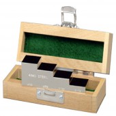
TI-SB Steel Test Blocks
- Precision Machined and Finished: Each test block is precision-machined and surface-finished to tight tolerances, ensuring excellent acoustic coupling and long-term dimensional stability.
- Includes NIST Certificate and Test Data: Supplied with a full calibration certificate traceable to NIST standards, including measured values and test data for complete verification accuracy.
- Includes Wooden Storage Box: Delivered in a durable hardwood storage case that protects the block from environmental effects and mechanical damage during storage or transport.
More details
TI-SB4 Steel Test Block
- Type: Uncertified steel test block for routine verification
- Design: Includes 4 and 6 precision-machined steps for quick accuracy checks
- Purpose: Designed for convenient confirmation of ultrasonic thickness gauge calibration without requiring NIST certification
More details
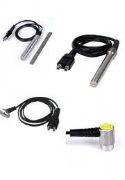
Category Wall Thickness Probes
Discover Checkline's probes for precise measurements on metals, plastics, and more, ideal for non-invasive structural inspections.
More details

